Email Clock Version 2

For the second version of the email clock, I wanted to simplify the networking aspect of it. I also wanted to make a prettier clock. So I changed technologies. For the controller, I used an Arduino module. For the net connection, I used a Lantronix Xport serial-to-ethernet module. And for the mail client, I wrote a perl script.
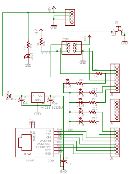
The wiring between the Arduino module and the Xport was simple: Arduino serial receive connects to the Xport’s serial send, and vice versa. I also connected LEDs to some of the Arduino pins to use as indicators for debugging. You can see in the code below when I was using LEDs to figure things out.
To connect the Xport to the Arduino module, I designed an Ardduino shield printed circuit board (PCB). I designed it in Eagle, a schematic and board layout program owned by Autodesk. Here’s the board schematic:
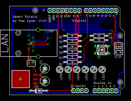
And here’s a picture of the board layout:
The Eagle files are in my gitHub repository. To get the board manufactured, I recommend sending the gerber files to Advanced Circuits or OSHPark. Advanced Circuits is a bit more expensive, but they’ve got a good circuit checking service online, FreeDFM. OSHPark’s easier to use.
The parts list for the board is also in the gitHub repository.
The system works like this: The Arduino opens a TCP socket to port 80 on the CGI server every few seconds. It makes a HTTP call for the CGI script. The script checks all my mail accounts, and returns the number of kilobytes. The clock then ticks forward one tick for every kilobyte of mail.