Microcontrollers can take sound in as an analog input, for crude measurements. While 8-bit ones (the Basic Stamp, BX-24, PIC, Arduino, etc) are not fast enough to read the frequency difference between various sounds, they can read sound levels. A line-level audio signal (which is what a typical CD or MP3 player produces) varies between -1V and 1V, a range of 2V total. If you raise that up so that it varies between, say, 3.5V and 1.5V, you can read it using the analog input on your microcontroller
First, if you have a microphone, you won’t be able to connect it directly. A microphone’s voltage, known as mic level voltage, is only a few millivolts at best. If you put it through a preamp such as a mixer board, or through an amplifier, you get a line level signal, which you can read.
A simple way to do this is to buy a preamplifier kit, something like the Velleman K1803 Universal Mono Preamplifier from Jameco (part no. 117612). For $8.95, it’ll save you some troubleshooting time, and cost about as much as the circuit below. Or you can build your own.
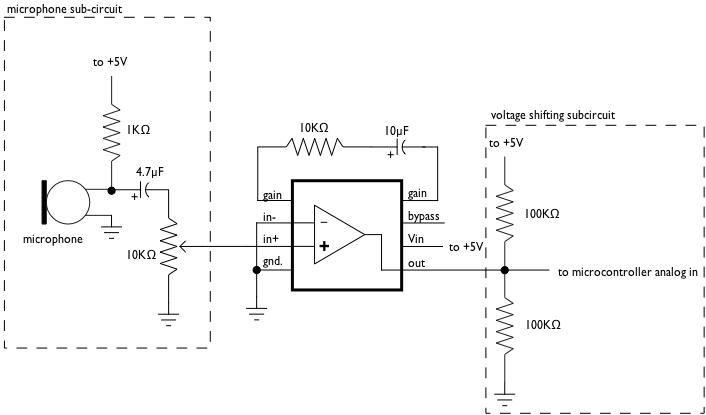
The following circuit uses a Condenser microphone element from Radio Shack (part no. 270-090C) and an amplifier chip also from Radio Shack (LM386 Audio Amplifier). The amplifier raises the microphone’s signal so it’s within line level tolerances, -1V to 1V. To raise that to a 1.5V to 3.5V range, we use a voltage divider (the two 100K resistors). Normally, the voltage between the resistors would be 2.5V (since their resistance is equal). When we add in the line level signal, we get 1.5V to 3.5V.
Note that the 10K variable pot is using all three pins of the potentiometer. The center pin goes to pin 2 of the amplifier, the end pins to the mic and pin 3, respectively. The variable resistor is your volume knob. I used an audio taper pot, since I wanted the curve of the pot to follow the sound’s volume.
Note that the capacitors are polarized electrolytic capacitors, so it matters which way they face.

In the BX-BASIC code, I found my base value (when all was silent) was about 512. So I subtracted that, took the absolute value of the result (so that negative numbers would always read as positive), and got a sound level varying between about 1 and 500. You may need to adjust these values depending on your setup.
dim soundIn as integer

Sub main()
    call delay(0.5)  ' start  program with a half-second delay

    do
        soundIn = abs(getADC(13)- 512)

        debug.print "soundIn = " ; cStr(soundIn)
    loop

End Sub
Here’s the same code in Wiring/Arduino:
void setup() {
	Serial.begin(9600);
}

void loop() {
	// read the audio in on analog 0:
	int soundLevel = analogRead(0) -512;
       Serial.print( "soundIn = ");
	Serial.println(soundLevel, DEC);
}
