This tutorial will show how to control multiple LED outputs from a microcontroller using a CD4099B addressable latch.
Parts you’ll need:
- CD4099B addressable latch
- Arduino microcontroller (Any model will do)
- 16 LEDs
How It Works
An addressable latch can either act as a multiplexer, or it can act as a latch. As a multiplexer, you can control one output at a time, but as a latch, you can control all of them, by setting the address pins, toggling the input, resetting the address pins,and toggling the input again. The reset pin and the write disable pin determine which way the latch operates, as follows:
| Reset | Write Disable | Mode |
| HIGH | HIGH | All outputs low |
| HIGH | LOW | multiplexer (one output on at a time) |
| LOW | LOW | Latch (any or all of outputs on at a time |
The Circuit
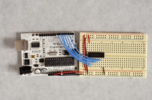
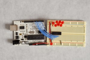
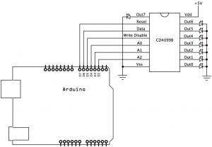
To control the addressable latch, you need a mimimum of 6 pins. In the images below, they’re connected to the Arduino as follows:
- Address pins:
- A0: digital 4
- A1: digital 3
- A0: digital 2
- Write disable pin: digital 5
- Data: pin: digital 6
- Reset: Digital 7
The LEDs are connected with their anodes attached to the latch outputs, and their cathodes to ground. The latch is acting as a current source for the LEDs.
|
|
|
The Code
First, assign the pns to I/O numbers. Put the address pins in an array, so you can iterate over them easily in order:
// set up the pins.  put the address pin numbers in an array
// so they're easy to iterate over:
const int resetPin = 7;
const int writeDisablePin = 5;
const int outputPin  = 6;
const int channel[] = {
  4, 3, 2};

The setup just initializes all the pins as outputs:

void setup() {
  // set all pins to output:
  for (int thisPin = 2; thisPin < 8; thisPin++) {
    pinMode(thisPin, OUTPUT);
  }
}
The loop iterates over all the channels twice. The first time, the reset pin is low, enabling latching, so all the LEDs come on one at a time. The second time, the reset pin is high, so that only one output can be on at a time:
void loop() {
  // enable latching by turning off the reset pin:
  digitalWrite(resetPin, LOW);
  // loop over the channels, lighting each one:
  for (int thisChannel = 0; thisChannel < 8; thisChannel++) {
    // disable the outputs:
    digitalWrite(writeDisablePin, HIGH);
    // set the address:
    latchWrite(thisChannel);
    // set the desired state:
    digitalWrite(outputPin, HIGH);
    // enable the output:
    digitalWrite(writeDisablePin, LOW);
    delay(500);
    Serial.begin(9600);
  }
  // disable latching by turning on the reset pin:
  digitalWrite(resetPin, HIGH);
  // loop over the channels, lighting each one:
  for (int thisChannel = 0; thisChannel < 8; thisChannel++) {
    // set the address:
    latchWrite(thisChannel);
    Serial.println(thisChannel, BIN);
    // set the desired state:
    digitalWrite(outputPin, HIGH);
    // enable the output:
    digitalWrite(writeDisablePin, LOW);
    delay(500);
  }
}
The latchWrite() method sets the address pins. It takes one parameter, the channel number that you plan to turn on. It iterates over the value you give it, determining the value of each of the three bits, and setting each of the three address pins appropriately. For example, imagine you want to control pin 6. In binary, 6 = 101. So address pin would be set to 1, A1 would be set to 0, and A2 would be set to 1. Tnen the latch’s data pin would be connected to output 6.
void latchWrite(int whichChannel) {
  // iterate over the number of pins you're using:
  for (int thisPin = 0; thisPin < 3; thisPin++) {
    // set the pin state based on the pin's bit value
    // in whichChannel:
    int pinState = bitRead(whichChannel, thisPin);
    digitalWrite(channel[thisPin],pinState);
  }
}
When the sketch runs, you should see all the LEDs come on one at a time, then see them all come on, additively. That’s the basics of how a latch works.
Here’s the sketch in its entirety for download.


