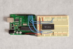
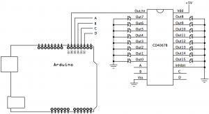
This tutorial will show how to control multiple LED outputs from a microcontroller using a CD4067 analog multiplexer.
This is a stub. More explanation will follow, but for now, here are schematics and code for Arduino.
Parts you’ll need:
- CD4067B multiplexer
- Arduino microcontroller
- LEDs
The Circuit
The code
/*

 Multiplexer output example
 Controls 16 outputs, one at a time, using a CD4067B multiplexer.

 This sketch loops over the 16 channels of a CD4067 multiplexer, switching
 the input to each output channel in turn.  It then fades up and down the
 input channel using analogWrite().

 The circuit:
 * CD4067 multiplexer attached as follows:
 - address pin A: digital I/O 2
 - address pin B: digital I/O 3
 - address pin C: digital I/O 4
 - address pin D: digital I/O 5
 - input pin: digital I/O pin 6
 - LEDs attached from each of the CD4067's output channels
 to ground

 created 21 May 2009
 by Tom Igoe

 https://tigoe.com/pcomp/code/category/arduinowiring/540 for more

 */

// put the address pin numbers in an array
// so they're easier to iterate over:
const int channel[] = {
  2, 3, 4, 5};

// the output pin channel (mux's input):
const int outputPin = 6;

void setup() {
  // set up all pins as output:
  for (int thisPin = 2; thisPin < 7; thisPin++) {
    pinMode(thisPin, OUTPUT);
  }
}

void loop() {
  // iterate over the 16 channels of the multiplexer:
  for (int thisChannel = 0; thisChannel < 16; thisChannel++) {
    // set the channel pins based on the channel you want:
    muxWrite(thisChannel);

    // fade the current channel up:
    for (int brightness = 0; brightness < 256; brightness++) {
      analogWrite(outputPin, brightness);
      delay(5);
    }
  }
}

void muxWrite(int whichChannel) {
  // iterate over the number of pins you're using:
  for (int thisPin = 0; thisPin < 4; thisPin++) {
    // calculate the state of this pin based on
    // its bit value in whichChannel:
    int pinState = bitRead(whichChannel, thisPin);
    // turn the pin on or off:
    digitalWrite(channel[thisPin],pinState);
  }
}


One Reply to “CD4067 Multiplexer used to control LEDs”
Comments are closed.