Created 31 March 2009, edited 1 Nov 2020
Once you’ve mastered microcontroller programming, you might be tempted to control a lot of LEDs. Lots of people have this desire once they master the basics. Many microcontrollers have a limited number of output pins, however, so you might think that limits how many LEDs you can control. I’ve written about a few different methods around this before in chapter 14 of Physical Computing and in this blog.
By matrixing your LEDs, you can control many more than the number of pins you have. For example, with the Arduino Uno and earlier models, you had up to 20 digital outputs (13 labeled digital I/O 0 through 13, plus the six analog outputs, which double as digital I/O 14 through 19). With 16 of those, you can control an 8×8 matrix of LEDs. That’s 64 LEDs. With the Arduino Mega, you have 54 digital I/O pins, so you can control a lot more. This example uses 32 of them to control 2 8×8 matrices, for a total of 128 LEDs from one controller.
To make this example, you’ll need:
- Arduino Mega
- Breadboard or prototyping shield.
- 8×8 LED matrix. I got mine in a surplus shop in China, but you can also get them from most electronics retailers
- male pin headers
- female pin headers
- Wires
Step 1: Figure out the LED Matrix pins
The hardest part of this project was figuring out the arrangement of the LED matrix pins. I didn’t have a data sheet for the matrix, only the code on the side of the part, HS-788AS. The only useful Google results I got on it were in Chinese, making them less useful to me personally. So I resorted to the old-fashioned method: I opened a notebook, put my multimeter on the diode check setting, and started touching pins.
I knew that the 16 pins of the matrix represented rows and columns, and that there are some pretty standard arrangements of pins, like this one I got from a different LED matrix:
My matrix didn’t match this pin configuration. But once I got one LED lit up, I knew that my positive meter lead was on a row, and my negative was on a column. Keeping the positive lead in place, I moved the negative lead in order to find the other columns. I found them in fairly quick order from there. They’re arranged like this:
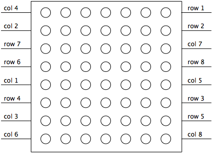
Caveat: your LED matrix will probably have a different pin arrangement, so read the data sheet, or use the method described above to find them for yourself.
Once I knew the pin configuration of the matrix, I connected its pins to the Mega. I had two matrices in hand, and each takes 16 pins, so I figured I’d use them both.
Step 2: Connect LED to Mega
To control a matrix, you connect both its rows and columns to your microcontroller. The columns are connected to the LEDs anodes (see Figure 1), so a column needs to be high for any of the LEDs in that column to turn on. The rows are connected to the LEDs cathodes, so the row needs to be low for an individual LED to turn on. If the row and the column are both high or both low, no voltage flows through the LED and it doesn’t turn on.
To control an individual LED, you set its column high and its row low. To control multiple LEDs in a row, you set the rows high, then take the column high, then set the lows row or high as appropriate; a low row will turn the corresponding LED on, and a high row will turn it off.
It doesn’t matter which pins of the microcontroller you connect the rows and columns to, because you can assign the pins in software. So I connected the pins in a way that made wiring easiest. The bare prototyping board looks like Figure 3:

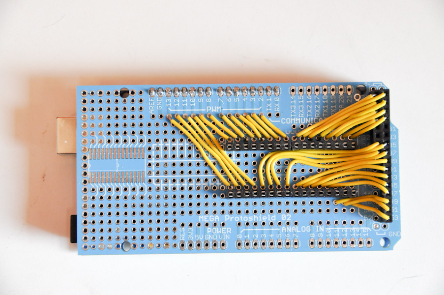
I added two rows of female headers to mount the matrices on, along with male headers to tie the pins on the low-numbered digital I/O pins (pins 2 through 13) to the matrices, since these pins have connections to other holes right next to them on the board. For the higher numbered I/O pins (pins 22 and above) I used female headers with long pins. Those pins have no other connections to the board, so I needed the female connections to add wires, and the long male pins to connect to the board below. This is what my board looked like after soldering:
Finally, I added the LED matrices, both facing the same way:

Step 3: Program
In order to control the rows and columns easily, I set up an array of rows and an array of columns for each matrix. Each array contains the pin number for the rows or columns of that matrix, in order:
int row[] = {
  22,23,27,49,28,45,43,25};

int col[] = {
  47,41,51,39,26,53,24,29};
The first program I wrote was very simple; it just turned on all the LEDs, like so:
void setup() {
  for (int thisPin = 0; thisPin < 8; thisPin++) {
    // initialize the output pins for matrix 1:
    pinMode(col[thisPin], OUTPUT);
    pinMode(row[thisPin], OUTPUT);
    // take the col pins (i.e. the cathodes) high to ensure that
    // the LEDS are off:
    digitalWrite(col[thisPin], HIGH);

    // initialize the output pins for matrix 2:
    pinMode(col2[thisPin], OUTPUT);
    pinMode(row2[thisPin], OUTPUT);

    // take the col pins (i.e. the cathodes) high to ensure that
    // the LEDS are off:
    digitalWrite(col2[thisPin], HIGH);
  }
}

void loop() {
  // light up the first matrix:
  // iterate over the rows (anodes):
  for (int thisrow = 0; thisrow < 8; thisrow++) {
    // take the row pin (anode) high:
    digitalWrite(row[thisrow], HIGH);
    // iterate over the cols (cathodes):
    for (int thiscol = 0; thiscol < 8; thiscol++) {
      // when the row is high and the col is low,
      // the LED where they meet turns on:
      digitalWrite(col[thiscol], LOW);
    }
    // take the row low to turn off all the LEDS in it:
     digitalWrite(row[thisrow], LOW);
  }

  // light up the second matrix:

  // iterate over the rows (anodes):
  for (int thisrow = 0; thisrow < 8; thisrow++) {
    // take the row pin (anode) high:
    digitalWrite(row2[thisrow], HIGH);
    // iterate over the cols (cathodes):
    for (int thiscol = 0; thiscol < 8; thiscol++) {
      // when the row is high and the col is low,
      // the LED where they meet turns on:
      digitalWrite(col2[thiscol], LOW);
    }
  }
}
The second program is a bit more complex. It uses two nested for loops, one to scan over the columns and one to scan the rows for each column. It turns on each LED, pauses, then turns it off:
void setup() {
  for (int thisPin = 0; thisPin < 8; thisPin++) {
    // initialize the output pins for matrix 1:
    pinMode(col[thisPin], OUTPUT);
    pinMode(row[thisPin], OUTPUT);
    // take the col pins (i.e. the cathodes) high to ensure that
    // the LEDS are off:
    digitalWrite(col[thisPin], HIGH);

    // initialize the output pins for matrix 2:
    pinMode(col2[thisPin], OUTPUT);
    pinMode(row2[thisPin], OUTPUT);

    // take the col pins (i.e. the cathodes) high to ensure that
    // the LEDS are off:
    digitalWrite(col2[thisPin], HIGH);
  }
}

void loop() {
  // light up the first matrix:
  // iterate over the rows (anodes):
  for (int thisrow = 0; thisrow < 8; thisrow++) {
    // take the row pin (anode) high:
    digitalWrite(row[thisrow], HIGH);
    // iterate over the cols (cathodes):
    for (int thiscol = 0; thiscol < 8; thiscol++) {
      // when the row is high and the col is low,
      // the LED where they meet turns on:
      digitalWrite(col[thiscol], LOW);
      delay(50);
      // take the col pin (cathode) high to turn the LED off:
      digitalWrite(col[thiscol], HIGH);
    }
    // take the row pin low to turn off the whole row:
    digitalWrite(row[thisrow], LOW);
  }

  // light up the second matrix:

  // iterate over the rows (anodes):
  for (int thisrow = 0; thisrow < 8; thisrow++) {
    // take the row pin (anode) high:
    digitalWrite(row2[thisrow], HIGH);
    // iterate over the cols (cathodes):
    for (int thiscol = 0; thiscol < 8; thiscol++) {
      // when the row is high and the col is low,
      // the LED where they meet turns on:
      digitalWrite(col2[thiscol], LOW);
      delay(50);
      // take the col pin (cathode) high to turn the LED off:
      digitalWrite(col2[thiscol], HIGH);
    }
    // take the row pin low to turn off the whole row:
    digitalWrite(row2[thisrow], LOW);
  }

  // do the same to go backwards, counting backwards:

  // second matrix in reverse:
  for (int thisrow = 7; thisrow > 0; thisrow--) {
    digitalWrite(row2[thisrow], HIGH);
    for (int thiscol = 7; thiscol >0; thiscol--) {
      digitalWrite(col2[thiscol], LOW);
      delay(50);
      digitalWrite(col2[thiscol], HIGH);
    }
    digitalWrite(row2[thisrow], LOW);
  }
  // first matrix in reverse:
  for (int thisrow = 7; thisrow > 0; thisrow--) {
    digitalWrite(row[thisrow], HIGH);
    for (int thiscol = 7; thiscol >0; thiscol--) {
      digitalWrite(col[thiscol], LOW);
      delay(50);
      digitalWrite(col[thiscol], HIGH);
    }
    digitalWrite(row[thisrow], LOW);
  }
}
That’s the basic idea, and now you’ve got Knight Rider for 128 LEDs with no extra parts! Enjoy. Here’s the whole sketch.
Once you have that working, try attaching potentiometers to analog inputs 0 and 1 and run this sketch.
Thanks to the good folks at Eyebeam for giving me a comfy place to work while I was on sabbatical in 2009!
6 Replies to “8×8 LED matrix control on an Arduino Mega”
Comments are closed.