This tutorial shows how to make an Arduino-based RFID reader that reads Mifare tags and stores them in EEPROM. It is a modification of Alex Zivanovic‘s code on Tinker.it. Thanks to Alex and Massimo Banzi for the reference. Once you’ve got it running, go on to the RFID to Web example, which provides a Processing interface sketch provides a GUI for the command-line interface written into the Arduino code.
The entire sketch can be downloaded here:
The Circuit
Parts:
- Solderless breadboard
- SM130 RFID read/write module
- RFID antenna
- Mifare RFID tags
- Arduino Pro Mini or Arduino Mini
- FTDI USB-to-serial cable
- 22AWG solid-core hookup wire in red, black, and blue
- 3 3mm LEDs or one tri-color common cathode LED
- row of five male headers, 0.1 inch spacing.
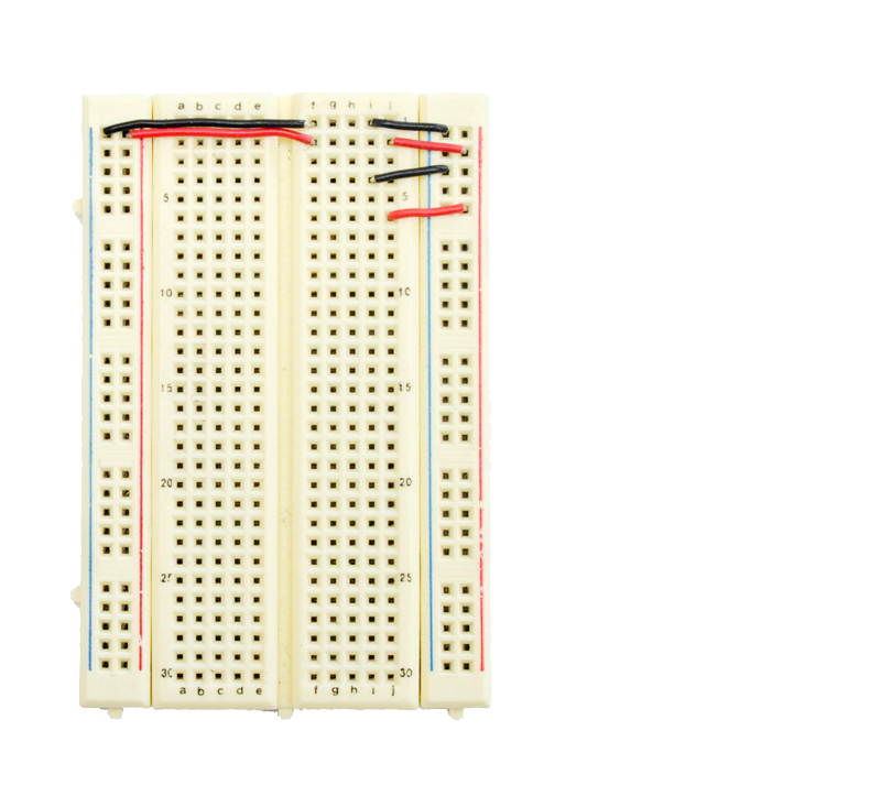
First, add wires to the breadboard to carry voltage and ground to the two vertical bus rows on either side:

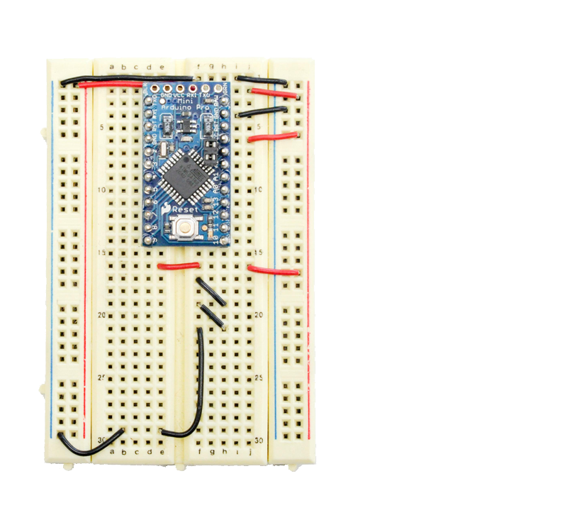
Next add an Arduino Pro Mini (a regular Arduino Mini will work also):

Next, add the voltage and ground wires for the SM130 RFID module. Make sure to leave slack in the lowest ground wire on the left. The SM130 module will plug into the same row of holes.

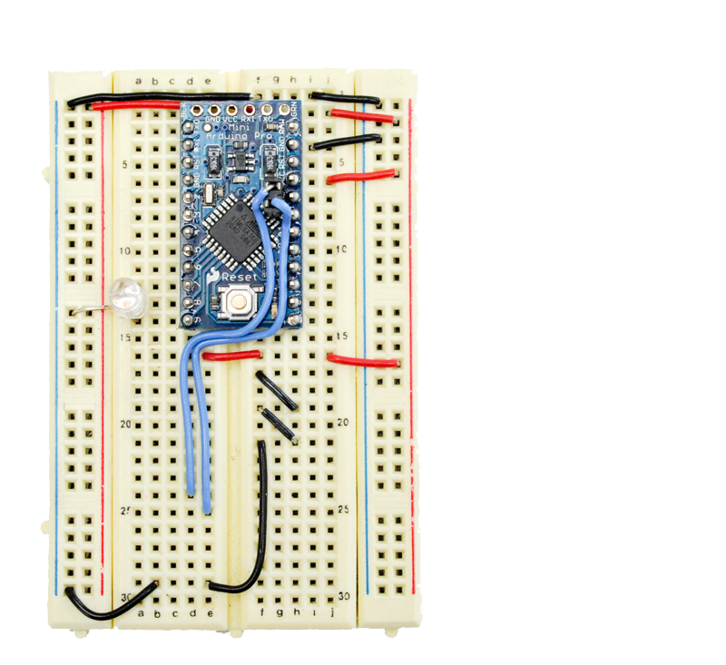
Next, add the I2C data and clock lines for the module. These connect to two female headers soldered on to the top of the Arduino Pro Mini. These headers connect to the SDA and SCL lines, which are on analog pins 4 and 5, respectively. See the Arduino Pro Mini page for details. Note: if you are using an Arduino Mini, the pins are in a different place. I added a tri-color LED to digital pins 7, 8, and 9, but you can use three regular LEDs instead.

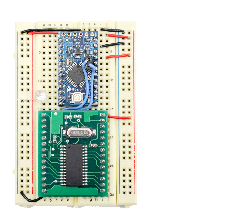
Next, add the SM130 module. The top lines up with the red voltage wires on the board. Make sure to leave a row of holes on the right side for the antenna.

Finally, add the antenna and the FTDI USB-to-serial cable. The top of the antenna lines up with the second pin down on the right hand side of the module. The green pin of the FTDI cable aligns with the right hand top pin of the Pro Mini.

The Arduino Code
The Arduino code for this project continually seeks new tags. When a new tag is acquired, it checks it against a list of tags stored in the EEPROM of the microcontroller. If it’s not there, it adds it to its database. It also sends and receives messages serially as a simple command-line interface. When it starts up, open the Arduino serial monitor, and you should see the following:
n - add card to database
c - clear entire database
d - delete card from database
p - print database
Waiting for card
If you bring a tag in range of the reader’s antenna, you’ll get the following message:
That tag is new
0:0A64EF28
Waiting for card
Do it again with the same tag and you’ll get:
That tag is already stored
0:0A64EF28
Waiting for card
Type c in the message box and send it and you’ll get a whole list of the database, like so:
0:0A64EF28
1:00000000
2:00000000
...
...
...
100:00000000
101:00000000
Later, you’ll use this serial interface to build a GUI for the reader. For first, take a look at the Arduino code in depth. You need to inclued the Wire library, which provides an API for the I2C connection to the reader, and the EEPROM library, which allows you to save data in the Arduino’s nonvolatile memory:
#include <Wire.h>
#include <EEPROM.h>
Next you’re going to define a few constants, including the maximum number of cards that you can save in memory (based on the size of the EEPROM) and the pin numbers for the indicator LEDs:
#define MAX_NO_CARDS 102
#define waitingLED 7
#define successLED 8
#define failureLED 9
Finally, a couple global variables for toggling the state of the waiting LED, and a four-byte array for holding the most recent tag read:
int toggleState = 0;    // state of the toggling LED
long toggleTime = 0;    // delay time of the toggling LED
byte tag[4];            // tag serial numbers are 4 bytes long
The setup() method initializes the reader via I2C, initializes the LED states, and sends the opening serial message. Then it waits 2 seconds for the reader to start up:
void setup() {
  Wire.begin();                      // join i2c bus
  Serial.begin(9600);                // set up serial port

  Wire.beginTransmission(0x42);      // the RFID reader's address is 42
  Wire.send(0x01);                   // Length
  Wire.send(0x80);                   // reset reader
  Wire.send(0x81);                   // Checksum
  Wire.endTransmission();

  // initialize the LEDs:
  pinMode(waitingLED, OUTPUT);
  pinMode(successLED, OUTPUT);
  pinMode(failureLED, OUTPUT);

  // print user instructions serially:
  Serial.println("n - add card to database");
  Serial.println("c - clear entire database");
  Serial.println("d - delete card from database");
  Serial.println("p - print database");

  // delay to allow reader startup time:
  delay(2000);
}
The main loop() method listens for serial data coming in, and takes appropriate action depending on what’s sent. If no serial data comes in, it runs seekNewTag() to keep the reader in seek mode. The 200 millisecond delay at the end of the main loop is there to keep the reader from being prompted too frequently:
void loop() {
  if (Serial.available() > 0) {
    // read the latest byte:
    char incomingByte = Serial.read();
    switch (incomingByte) {
    case 'n':            // if user enters 'n' then store tag number
      seekNewTag();
      break;
    case 'c':
      eraseEEPROM();    // if user enters 'c' then erase database
      Serial.println("Database deleted");
      break;
    case 'd':           // if user enters 'd' then delete the last tag
      seekAndDeleteTag();
      break;
    case'p':            // if user enters 'p' then print the database
      printTags();
      break;
    }
  }
  else {
    //if there's no serial data coming in,
    // the default action is to seek new tags:
    seekNewTag();
  }
  // delay before next command to the reader:
  delay(200);
}
If you send the Arduino a c, it erases the EEPROM with the following method:
// erase the entire EEPROM memory storage:
void eraseEEPROM(){
  for(int i = 0; i < 512; i++){
    EEPROM.write(i, 0);
  }
}
When a new tag is read, the following method saves it to EEPROM:
// writes tag number in a location:
void writeTag(int startingAddress, byte byte0, byte byte1, byte byte2, byte byte3){
  EEPROM.write( startingAddress*5, byte(1));
  EEPROM.write(startingAddress*5+1, byte0);
  EEPROM.write(startingAddress*5+2, byte1);
  EEPROM.write(startingAddress*5+3, byte2);
  EEPROM.write(startingAddress*5+4, byte3);

}
If you send the Arduino a d, it deletes the most recently read tag using the following method:
// delete tag from a specified location
void deleteTag(int startingAddress){
  EEPROM.write( startingAddress*5, byte(0));
  EEPROM.write(startingAddress*5+1, byte(0));
  EEPROM.write(startingAddress*5+2, byte(0));
  EEPROM.write(startingAddress*5+3, byte(0));
  EEPROM.write(startingAddress*5+4, byte(0));
}
The following method checks to find the first empty space in the EEPROM database:
// find the first empty entry in the database:
int findEmptyTag(){
  for (int startingAddress = 0; startingAddress< MAX_NO_CARDS; startingAddress++){
    byte value = EEPROM.read(startingAddress*5);
    if (value == byte(0)) {
      return(startingAddress);
    }
  }
  return(200);
}
If you send the Arduino a p, it prints the entire database using the following two methods:
// print the entire database
void printTags(){
  for (int thisTag = 0; thisTag< MAX_NO_CARDS; thisTag++){
    printOneTag(thisTag);
  }
}

// print a single tag given the tag's address:
void printOneTag(int address) {
  Serial.print(address);
  Serial.print(":");
  for (int offset = 1; offset < 5; offset++) {
    int thisByte = int(EEPROM.read(address*5+offset));
    // if the byte is less than 16, i.e. only one hex character
    // add a leading 0:
    if (thisByte < 0x10) {
      Serial.print("0");
    }
    // print the value:
    Serial.print(thisByte,HEX);
  }
  // add a final linefeed and carriage return:
  Serial.println();
}
This method reads the EEPROM database to find a given tag:
//lookup tag in the database:
int lookupTag(byte byte0, byte byte1, byte byte2, byte byte3){
  for (int thisCard = 0; thisCard< MAX_NO_CARDS; thisCard++){
    byte value = EEPROM.read(thisCard*5);
    if (value != byte(0)){                    //it is a valid tag
      //see if all four bytes are the same as the ones we're looking for
      if(byte0 == EEPROM.read(thisCard*5+1) && byte1 == EEPROM.read(thisCard*5+2)
        && byte2 == EEPROM.read(thisCard*5+3) && byte3 == EEPROM.read(thisCard*5+4)) {
        return(thisCard);
      }
    }
  }
  // if you don't find the tag, return 200;
  return(200);
}
This method reads a tag from the EEPROM and saves it in the byte array variable called tag[]:
int getTag(){
  byte count = 0;
  byte valid = 0;
  byte byteFromReader = 0;

  Wire.beginTransmission(0x42);
  Wire.send(0x01);           // Length
  Wire.send(0x82);           // Seek for tags
  Wire.send(0x83);           // Checksum
  Wire.endTransmission();

  delay(100);
  Wire.requestFrom(0x42, 8); // get data (8 bytes) from reader

  count = 0;                 // keeps track of which byte it is in the response from the reader
  valid = 0;                 // used to indicate that there is a tag there
  while(Wire.available())  { // while data is coming from the reader
    byteFromReader = Wire.receive();
    // no RFID found: reader sends character 2:
    if ((count == 0) && (byteFromReader == 2)) {
      return(0);
    }
    if ((count == 0) && (byteFromReader== 6)) {
      //if reader sends 6, the tag serial number is coming:
      valid = 1;
    }
    count++;

    if ((valid == 1) && (count > 3) && (count < 8)) {
      // strip out the header bytes  :
      tag[count-4] = byteFromReader;
    }
    // all four bytes received: tag serial number complete:
    if ((valid == 1) && (count == 8)) {
      return(1);
    }
  }
}
This method prompts the reader into seek mode and reads new tags. However, if new serial data is received while the reader is waiting, it breaks out of the method and returns to the main loop. If no serial data is received, it reads an incoming tag and saves it to EEPROM. It also blinks the success LED when a tag is read and saved successfully. If the EEPROM memory is full, it blinks the failure LED:
void seekNewTag() {
  Serial.println("Waiting for card");
  while(getTag() == 0){
    // wait for tag
    if (millis() - toggleTime > 1000) {
      toggle(waitingLED);
      toggleTime  = millis();
    }
    // unless you get a byte of serial data,
    if (Serial. available()) {
      // break out of the while loop
      // and out of the seekNewTag() method:
      return;
    }
  }

  // look it up in the database:
  int tagToCheck = lookupTag(tag[0], tag[1], tag[2], tag[3]);

  if (tagToCheck != 200){
    Serial.println("That tag is already stored");
    printOneTag(tagToCheck);
  }
  else {
    int emptyTagLocation = findEmptyTag();
    if (emptyTagLocation != 200){
      writeTag(emptyTagLocation, tag[0], tag[1], tag[2], tag[3]);
      Serial.println("That tag is new");
      printOneTag(emptyTagLocation);
      blink(successLED, 100, 1);
    }
    else {
      Serial.println("Maximum number of cards stored");
      blink(failureLED, 50, 10);
    }
  }
}
The following method looks up a tag in the EEPROM database and deletes it from the database. It’s called when you send the Arduino a d.
void seekAndDeleteTag() {
  Serial.println("Deleting the next card");
  Serial.println("Waiting for card");
  while(getTag() == 0){
    // do nothing; wait for tag
    // unless you get a byte of serial data,
    if (Serial. available()) {
      // break out of the while loop
      // and out of the method:
      return;
    }
  }
  int tagToDelete = lookupTag(tag[0], tag[1], tag[2], tag[3]);
  if (tagToDelete == 200){
    Serial.print("That tag is not stored");
  }
  else {
    deleteTag(tagToDelete);
  }
}
The final two methods are used to blink the LEDs:
void toggle(int thisLED) {
  toggleState = !toggleState;
  digitalWrite(thisLED, toggleState);
}

void blink(int thisLED, int interval, int count) {
  for (int i = 0; i < count; i++) {
    digitalWrite(thisLED, HIGH);
    delay(interval/2);
    digitalWrite(thisLED, LOW);
    delay(interval/2);
  }
}
That’s the whole program. Once you’ve entered it, upload it to your Arduino and try reading tags with the serial monitor open. Try also sending some of the serial commands to see them in action. Then move on to programming the Processing interface.
Here’s the Arduino code in its entirety:
That’s it! Once you’ve tested it out in the serial monitor, go on to the RFID to Web tutorial, which shows you how to make a Processing sketch for a GUI that interfaces with this reader, uploads tags to a PHP script and retrieves data from a database.
One Reply to “Arduino-based RFID reader”
Comments are closed.