Making prototype circuits
using a solderless breadboard
Many people are confused the first time that they have to build a circuit. How to connect the components together? The easiest way to get started is by using a solderless breadboard. A breadboard is a tool for holding the components of your circuit, and connecting them together. It’s got holes that are a good size for hookup wires and the ends of most components, so you can push wires and components in and pull them out without much trouble.
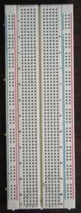 At right is a typical breadboard. There are several rows of holes for components. The holes on the breadboard are separated by 0.1-inch spaces, and are organized in many short rows in the center, and in two long rows down each side of the board. The short horizontal rows in the middle are separated by a center divider.
The pattern varies from model to model; some breadboards have only one strip down each side (like this model from Radio Shack), others have multiple side rows, and so forth. The basic model, with many horizontal rows separated by a central divider and one or two long side rows, is what we’ll focus on.
On each side of the board are two long rows of holes, with a blue or a red line next to each row. All the holes in each of these lines are connected together with a strip of metal in the back. In the center are several short rows of holes separated by a central divider. All of the five holes in each row in the center are connected with a metal strip as well. This allows you to use the holes in any given row to connect components together. To see which holes are connected to which, take a multimeter and a couple of wires, set the multimeter to measure continuity, stick the two wires in two holes, and measure them with the multimeter. If the meter indicates continuity, then the two holes in question are connected.
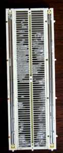 This image of the back of a breadboard may help to clear up how the holes on the front of the board are connected. The backing of the board has been removed (don’t remove the backing on your own board! It will make the board useless) to expose the metal strips connecting the holes. You can clearly see the short strips in the center separated by the divider, and the long strips down the side.
 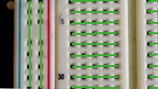 The detail photo to the right illustrates how the holes and strips are related.
The reason for the center divider is so that we can mount integrated circuit chips, like a microprocessor, on the breadboard. IC chips typically have two rows of pins that we need to connect other components to. The center row isolates the two rows from each other, and gives us several holes connected to each pin, so we can connect other components.
When you start to put components on your breadboard, avoid adding, removing, or changing components on a breadboard whenever the board is powered. You risk shocking yourself and damaging your components.
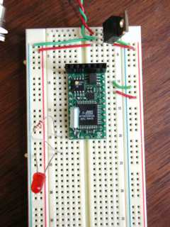 At left is a typical use of a breadboard. We have an IC chip (in this case a BX-24 microcontroller) straddling the center divider, connected to several of the rows of middle holes. At the top, a 7805 5V DC voltage regulator is connected to three of the middle rows. The 7805 regulator is also connected to the side rows of pins. Its ground pin is connected to the blue rows of holes, and its +5V output is connected to the red rows of holes. This way, the red rows of holes can be used to supply 5V, and the blue holes allow us to connect to ground. Note how the BX-24 is grounded by connecting the row that its ground pin is in to the blue rows with a short green wire. It is also powered by connecting the row that its +5V pin is in to the red rows with a short red wire. Note also the LED and resistor connected to the BX-24’s bottom left pin (pin 12).
In this detail , you can see that the resistor and the LED are connected in series between the BX-24 and ground (the blue row). A second row of middle holes is used to connect the LED to the resistor. Compare it to this wrong detail . Can you see what’s wrong with the second circuit? The resistor is short circuited, because both of its ends are connected to the same row!
In the first detail above, you saw components connected in series, by connecting one end of one component to a row, the other end to a second row, one end of a second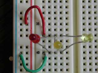 component to the second row as well, and the other end of the second component to a third row. Components can also be connected in parallel on a breadboard. At right, the three LED’s are connected in parallel using two rows. They are then connected to power and ground by connecting the rows to the red power row and the blue ground row.
Many options are possible using a breadboard, which is what makes them very useful and convenient for building circuits. Once you understand which holes are connected to each other (and which ones are not), you can build any circuit very quickly.
It’s a good idea to keep your circuits neat. When possible, shorten the leads on components so there is no bare metal sticking up from the breadboard. Make sure no wires cross each other with metal touching (this is the biggest source of short circuits on a breadboard). Lay things out as sensibly as possible, so each component of the circuit is near the components it needs to connect to. Use wires when needed to separate parts of the circuit that are crowded together. Use consistent colors of wires when possible; for example, use green or black for ground connections, red for power connections, white or blue for data connections, and so forth. This will make your troubleshooting much easier.
One Reply to “Breadboards”
Comments are closed.